No.
|
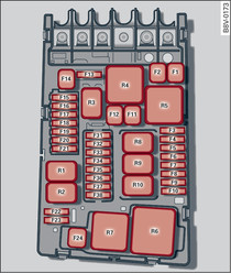
Electrical equipment
|
amps
|
F1
|
ESC control unit
|
40
|
F2
|
ESC control unit
|
40
|
F3
|
Engine control unit (petrol/diesel)
|
15/30
|
F4
|
Engine cooling, water recirculation pump, oil pressure control valve (oil pump), camshaft, exhaust system, overrun air recirculation shut-off valve, solenoid valve, compressor solenoid valve, charge pressure positioner, engine components, oil spray jet control valve, tank valve, supplementary heater relay coils (1+2), secondary air pump relay, Active Cylinder Management, pressure valve, ethanol sensor, sensor for extended service intervals
|
5/10
|
F5
|
High-pressure pump, pressure valve, engine components, fuel injectors, adjuster unit, tank system, coil ignition modules, exhaust gas sensor, PremAir sensor
|
7.5/10
|
F6
|
Brake light sensor
|
5
|
F7
|
Water recirculation pump, high-pressure pump, coolant pump, thermomanagement, heating water pump, oil pressure control valve (oil pump), fan louvre
|
7.5/10
|
F8
|
Lambda probe, tank system
|
10/15
|
F9
|
Water recirculation pump, ignition coil, camshaft, exhaust system, electric exhaust flap, control unit for automatic glow period, heater for crankcase, air mass meter
|
5/10/20
|
F10
|
Fuel injectors, fuel control unit
|
15/20
|
F11
|
Supplementary heater, heating rod 2
|
40
|
F12
|
Supplementary heater, heating rod 3
|
40
|
F13
|
Automatic gearbox control unit
|
15/30
|
F15
|
Horn
|
15
|
F16
|
Ignition coil
|
20
|
F17
|
ESC control unit, engine control unit
|
7.5
|
F18
|
Terminal 30 (reference voltage)
|
5
|
F19
|
Windscreen wipers
|
30
|
F20
|
Horn
|
10
|
F22
|
Terminal 50, diagnostics
|
5
|
F24
|
Supplementary heater, heating rod 1
|
40
|
F31
|
LED headlight (left side)
|
5
|
F32
|
LED headlight (right side)
|
5
|
F37
|
Auxiliary heating
|
20
|